Fin Alignment Analysis
This is bad.
I know this is bad, you know this is bad. But how bad? Can we quantify the badness?
Measurements
I don’t honestly know where to begin, but I figured that if I poke and prod at some measurements, some kind of picture will begin to emerge.
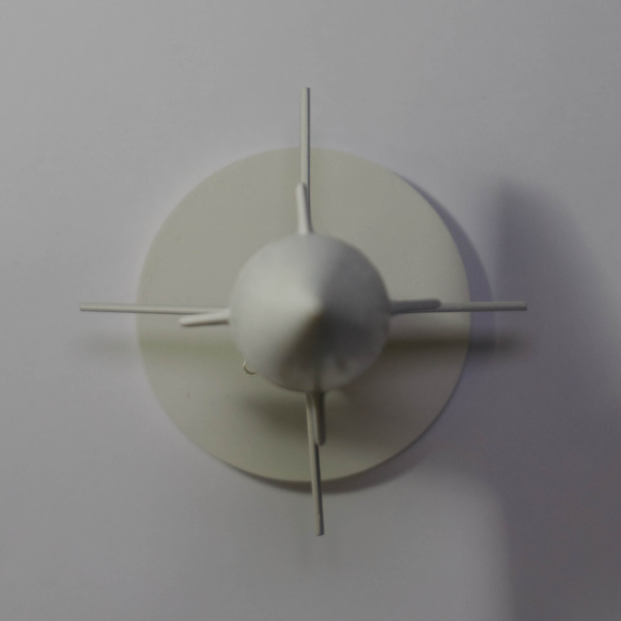
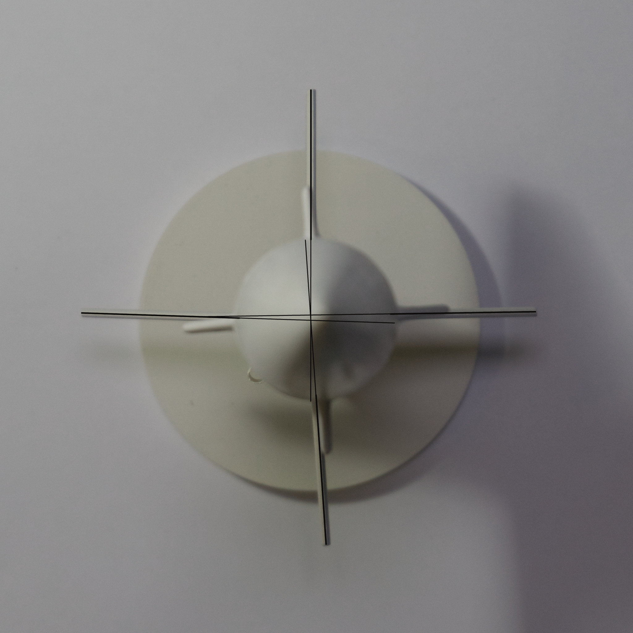
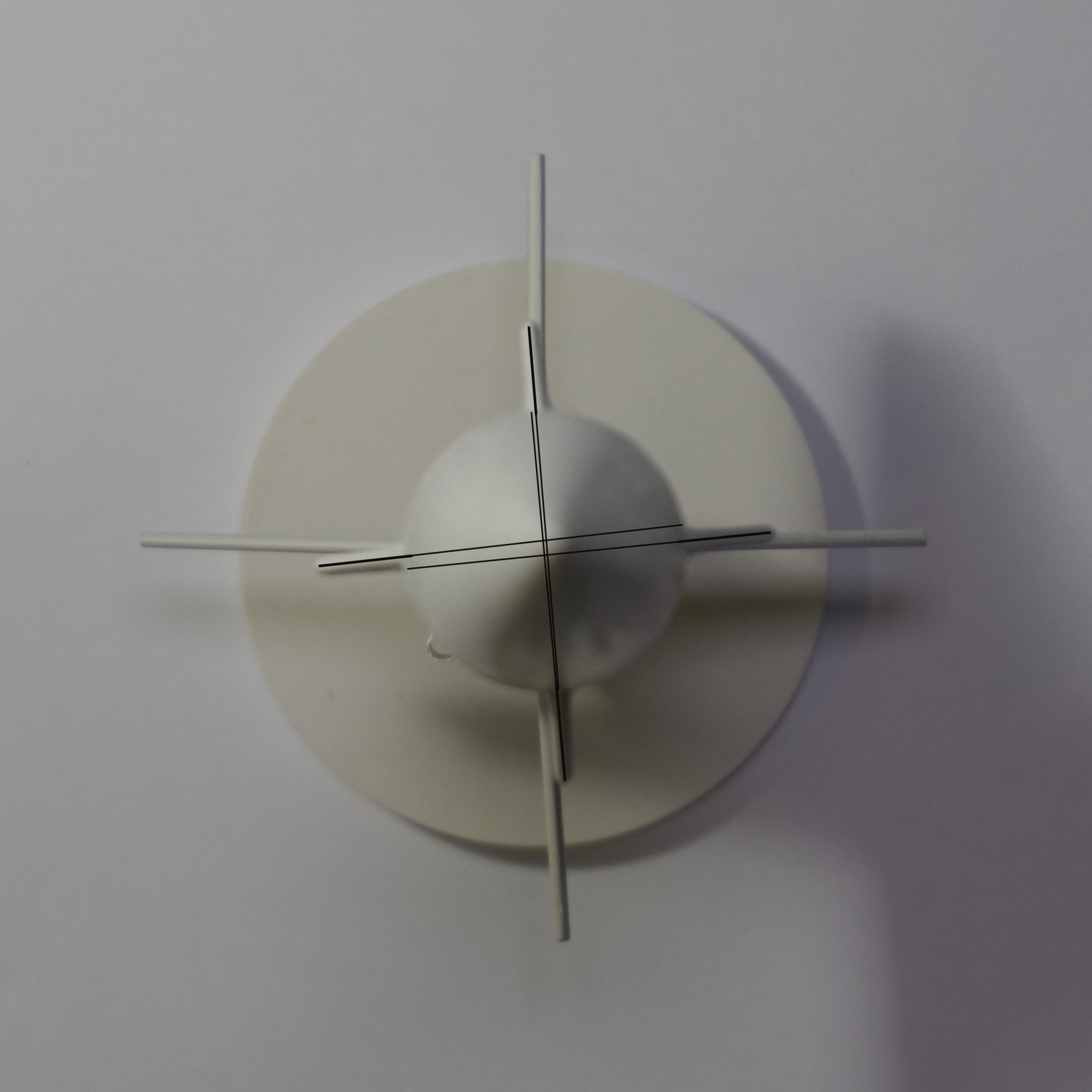
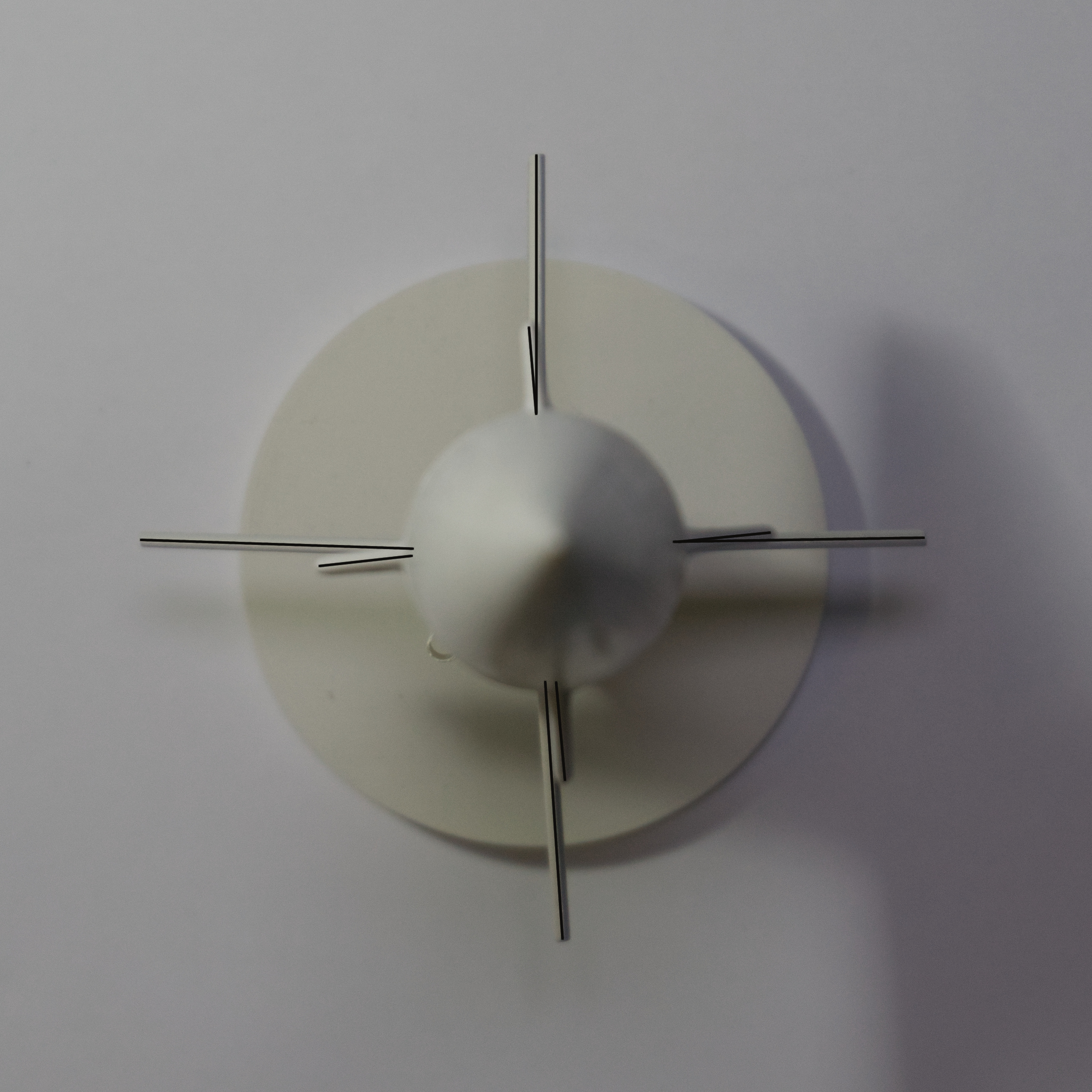
I took a photo of Frank from as close to straight overhead as I could get. Naturally, it didn’t come out perfectly, but I’m pleased with the result. That photo got dragged into GIMP 2.10 and had a few helper lines drawn on top. Then, I switched over to GIMP’s angle measurement tool and made a not of the apparent angles between the fins.
For the purposes of this analysis, the fin at the top of the image will be fin A, and the other fins will be B, C, and D, going clockwise. The launch lug is between fins C and D. The base image has been rotated so that aft fin A is aligned with the vertical axis of the picture, and will serve as our 0°.
Aft Fins
| Fins | Value (°) | Deviation from Ideal (°) | Notes |
|---|---|---|---|
| A, B | 88.98 | 1.02 | |
| B, C | 87.08 | 2.92 | |
| C, D | 95.89 | 5.89 | |
| D, A | 88.14 | 1.86 | |
| A, C | 175.95 | 4.05 | Intersection is close to craft’s midline |
| B, D | 177.09 | 2.91 | Intersection is outside the craft’s hull |
The average deviation from ideal is 2.92° among adjacent fin pairs, which is less than I thought it would be. “Ideal” is 90° for adjacent fin pairs and 180° for opposing pairs.
If we imagine extending the fins towards the midline of the rocket unitl they intersect, seeing where that intersection takes place can be another way of determining how “off” the fins are. For the A/C pair, that intersection occurred close to the midline. For the B/D pair, however, the alignment of fin D is so bad that the alignment occurs outside the hull of the rocket, well within fin D.
Forward Fins
| Fins | Value (°) | Deviation from Ideal (°) | Notes |
|---|---|---|---|
| A, B | 89.07 | 0.93 | |
| B, C | 90.68 | 0.68 | |
| C, D | 88.99 | 1.01 | |
| D, A | 91.63 | 1.63 | |
| A, C | 179.11 | 0.89 | Intersection at hull edge |
| B, D | N/A | N/A | Cannot measure |
The average deviation from ideal is 1.06°, lower than the aft fins. Interestingly, fins B and D are so near parallel that their intersection is somewhere way off in the distance and can’t be measured.
All
| Fin | Fore/Aft Difference (°) | Intersection Location |
|---|---|---|
| A | 4.76 | Near surface of hull |
| B | 4.38 | Near surface of hull |
| C | 1.39 | Far outside far side of hull |
| D | 8.18 | Inside hull |
Now this is where things start to go off the rails. It would have been one thing if the fins were consistently misaligned, but they aren’t: the inconsistency isn’t even consistent.
Parting Thoughts
It may also be beneficial to check how far apart the fins themselves are spaced, and to check for cant. Once I determine a way of doing these, I may or may not get around to it. I don’t plan on flying this rocket again, but these analytical methods may have usefulness somewhere down the line, and Frank is a great craft upon which to test.